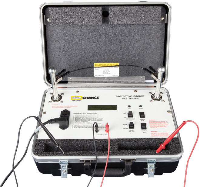
- Microprocessor technology for easy, accurate diagnostics
- Self-contained, portable convenience
- Simple, one-button testing
- Troubleshooting mode
This tester provides an easy way for an electric utility to check the resistance in protective grounding sets used by line personnel.
Powered by 120 VAC, the tester applies Direct Current across the test specimen. A seven-minute videotape, included with each unit, shows how simple the tester is to use.
Procedure details are given in the instruction manual. All components store in the tester’s integral carrying case.
Simple, one-button testing
From pushing a single button, the digital display shows the resistance measured in milliohms compared with a preset threshold for the size grounding cable selected (#2, 1/0, 2/0 or 4/0).
A green “Pass” or red “Fail” light also indicates the test result’s relation to the threshold.
For system-specific requirements, the user can easily change the Tester’s basis for voltage allowed across a lineworker, which comes factory preset at 100 Volts.
Adjusting this limit automatically causes a corresponding shift in the resistance thresholds for all the grounding cable sizes.
Regardless of the voltage-allowed setting or cable size selected, the Tester displays the resistance of each specimen in milliohms with ±1% accuracy, from 1 micro-ohm to 6.5 ohms.
The utility must establish the maximum resistance allowed for protective grounding sets used on each specific area of its systems.
How the utility calculates these values depends on several factors outlined in the Tester instructions.
Sample calculations with reference tables and charts are given in the manual.
Troubleshooting Mode
If a ground set does not pass the initial test, the Tester can help isolate the problems. Often, the source of high resistance can be remedied by simple repairs to the cable set. Retesting then can quickly verify the effects of repairs.
For this troubleshooting mode, a pair of test probes are furnished to plug into the Tester. A switch activates them instead of the ball-stud terminals. The probes then are used to test across each contact interface in the ground set. The results display in milliohms, just as in the first test mode.
Optional terminals for special ground sets
The Tester’s standard ball-stud terminals accept most types of ground clamps, including Chance ball-socket clamps.
To test special-application grounding sets for underground distribution transformers or switchgear, two optional adapters shown below are available as separate items.
Ordering Information
Included with each CHANCE® Protective-Grounding-Set Tester:
- Self-contained carry case
- 2 Ball-stud terminals
- DVD demonstration video
- Instruction manual
- 2 Troubleshooting probes
- Self-test cable
| Model# | Description | Weight |
|---|---|---|
| C4033220 | Protective-Ground-Set Tester | 17 lb./7.65 kg. |
Optional Adapters
| Model# | Description | Weight |
|---|---|---|
| T4033159 | Straight Stud Terminal for 15 and 25 kV | 3/4 lb./0.225 kg. |
| C4033449 | Elbow Adapter 15/25 kV | 1 lb./0.45 kg. |
| PSC4032947 | Elbow Adapter 35 kV | 1-1/4 lb./0.6 kg. |
